
| Categories | Electric Generator Manuals, Yamaha Generator Manuals |
|---|---|
| Tags | Yamaha EF4000DE, Yamaha EF5200DE, Yamaha EF6600DE, Yamaha YG4000D, Yamaha YG5200D, Yamaha YG6600D, Yamaha YG6600DE |
| Download File |
|
| Document File Type | |
| Copyright | Attribution Non-commercial |
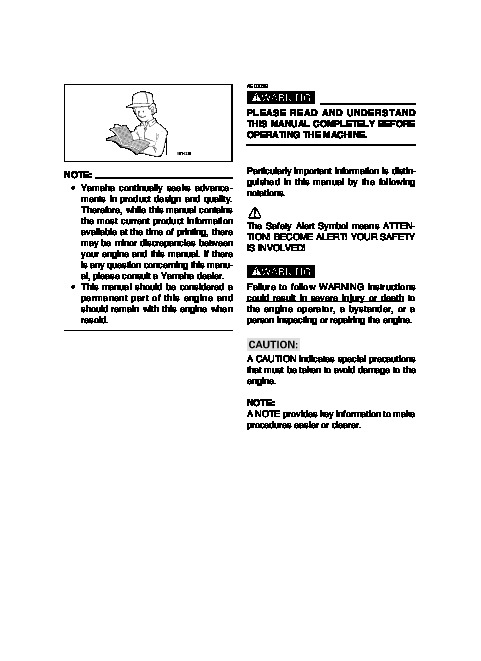
Generator OWNER’S MANUAL EF4000DE EF5200DE EF6600DE YG4000D YG5200D YG6600D YG6600DE LIT-19626-01-15 7WV-28199-11 AE00002 INTRODUCTION Congratulations on your purchase of your new Yamaha. This manual will provide you with a good basic understanding of the operation and maintenance of this machine. If you have any questions regarding the operation or maintenance of your machine, please consult a Yamaha dealer. PRI-I.D. NUMBER: MODEL PRI-I.D. CODE AE00012 SERIAL No. IDENTIFICATION NUMBER RECORDS Record your Primary I.D., and serial numbers in the spaces provided, to assist you in ordering spare parts from a Yamaha dealer.
Power Equipment User Manual Free Download. Electric Generator for Power Manual. Free Manual Download PDF.
Also record and keep these I.D. numbers in a separate place in case your machine is stolen. AE00011 MACHINE IDENTIFICATION The machine serial number is stamped in the location as shown. NOTE: The first three digits of these numbers are for model identification; the remaining digits are the unit production number. Keep a record of these numbers for reference when ordering parts from a Yamaha dealer. 790-060 AE00022 EF4000DE/EF5200DE/EF6600DE YG4000D/YG5200D/YG6600D/YG6600DE OWNER’S MANUAL 2003 by Yamaha Motor Corporation, U.S.A. 1st Edition, August 2003 Any reprinting or unauthorized use without the written permission of Yamaha Motor Corporation, U.S.A. is expressly prohibited. Printed in Japan. P/N LIT-19626-01-15 AE00032 w PLEASE READ AND UNDERSTAND THIS MANUAL COMPLETELY BEFORE OPERATING THE MACHINE. NOTE: 9 Yamaha continually seeks advancements in product design and quality. Therefore, while this manual contains the most current product information available at the time of printing, there may be minor discrepancies between your engine and this manual. If there is any question concerning this manual, please consult a Yamaha dealer. 9 This manual should be considered a permanent part of this engine and should remain with this engine when resold. Particularly important information is distinguished in this manual by the following notations. The Safety Alert Symbol means ATTENTION! BECOME ALERT! YOUR SAFETY IS INVOLVED! w Failure to follow WARNING instructions could result in severe injury or death to the engine operator, a bystander, or a person inspecting or repairing the engine. cC A CAUTION indicates special precautions that must be taken to avoid damage to the engine. NOTE: A NOTE provides key information to make procedures easier or clearer. AE00041 CONTENTS LIMITED WARRANTY (EF- AND EDL-SERIES) 1 LIMITED WARRANTY (EC- AND YG-SERIES) 2 LOCATION OF IMPORTANT LABELS.4 SAFETY INFORMATION .6 EXHAUST FUMES ARE POISONOUS 6 FUEL IS HIGHLY FLAMMABLE AND POISONOUS 6 ENGINE AND MUFFLER MAY BE HOT 6 ELECTRIC SHOCK PREVENTION 7 CONNECTION NOTES 8 CONNECTION 8 EXTENSION CORD NOTES 8 CONTROL FUNCTION 9 DESCRIPTION .9 CONTROL BOX 11 OIL WARNING SYSTEM 13 ENGINE SWITCH .13 STARTER SWITCH 13 AC SWITCH (N.F.B.) 14 ECONOMY IDLE SWITCH .14 VOLTAGE ADJUSTER .15 G.F.C.I. RECEPTACLE 15 PRE-OPERATION CHECK .16 FUEL .16 ENGINE OIL .17 GROUND (Earth) 18 BATTERY .18 OPERATION 19 STARTING THE ENGINE .19 APPLICATION RANGE 21 CONNECTION 22 STOPPING THE ENGINE 24 PERIODIC MAINTENANCE 25 MAINTENANCE CHART 25 SPARK PLUG INSPECTION 27 CARBURETOR ADJUSTMENT .27 ENGINE OIL REPLACEMENT .28 AIR FILTER 29 FUEL COCK .30 FUEL TANK FILTER .30 MUFFLER SCREEN AND SPARK ARRESTER 31 BATTERY .34 FUSE REPLACEMENT 35 G.F.C.I. RECEPTACLE TEST 35 TROUBLESHOOTING 36 STORAGE .40 DRAIN THE FUEL 40 ENGINE 40 BATTERY .41 EXHAUST EMISSION CONTROL SYSTEM AND COMPONENTS .42 SPECIFICATIONS .43 DIMENSIONS .43 ENGINE 43 GENERATOR .43 WIRING DIAGRAM EF4000DE 44 EF5200DE 45 EF6600DE 46 YG4000D 47 YG5200D 48 YG6600D 49 YG6600DE 50 BATTERY TRAY INSTALLATION 51 ENGINE HANGER INSTALLATION .51 OPTIONAL PARTS INSTALLATION 51 AE01119 YAMAHA MOTOR CORPORATION U.S.A. EF- AND EDL-SERIES GENERATOR LIMITED WARRANTY Yamaha Motor Corporation, U.S.A. hereby warrants that new Yamaha consumer generators purchased from an authorized Yamaha consumer generator dealer in the continental United States will be free from defects in material and workmanship for the period of time stated herein, subject to certain stated limitations. THE PERIOD OF WARRANTY Any new EFseries or EDL-series Yamaha Generator purchased for private, non-commercial use from an authorized Yamaha consumer generator dealer in the continental United States will be warranted against defects in material or workmanship for a period two (2) years from date of purchase, subject to exclusions noted herein. Any Yamaha non-commercial generator purchased and utilized for commercial or rental applications will be warranted for a period one (1) year from the date of purchase, subject to exclusions noted herein. DURING THE PERIOD OF WARRANTY any authorized Yamaha consumer generator dealer will, free of charge, repair or replace, at Yamaha’s option, any part adjudged defective by Yamaha due to faulty workmanship or material from the factory. Parts used in warranty repairs will be warranted for the balance of the product’s warranty period. All parts replaced under warranty become property of Yamaha Motor Corporation U.S.A. GENERAL EXCLUSIONS from this warranty shall include any failures caused by: a. Installation of parts or accessories that are not qualitatively equivalent to genuine Yamaha parts. b. Abnormal strain, neglect, or abuse. c. Lack of proper maintenance. d. Accident or collision damage. SPECIFIC EXCLUSIONS from this warranty shall include parts replaced due to normal wear or routine maintenance. THE CUSTOMER’S RESPONSIBILITY under this warranty shall be to: 1. Operate and maintain the generator as specified in the appropriate Owner’s Manual; 2. Give notice to an authorized Yamaha consumer generator dealer of any and all apparent defects within ten (10) days after discovery, and make the unit available at that time for inspection and repairs at such dealer’s place of business. WARRANTY TRANSFER: To transfer the warranty from the original purchaser to any subsequent purchaser(s), it is imperative that the unit be inspected and registered for warranty by an authorized Yamaha consumer generator dealer. In order for this warranty to remain in effect, this inspection and registration must take place within ten (10) days after transfer. An inspection and registration fee will be charged for this service. In no case will the warranty be extended beyond the original period. YAMAHA MOTOR CORPORATION, U.S.A. MAKES NO OTHER WARRANTY OF ANY KIND, EXPRESSED OR IMPLIED. ALL IMPLIED WARRANTIES OF MERCHANTABILITY AND FITNESS FOR A PARTICULAR PURPOSE WHICH EXCEED THE OBLIGATIONS AND TIME LIMITS STATED IN THIS WARRANTY ARE HEREBY DISCLAIMED BY YAMAHA MOTOR CORPORATION, U.S.A. AND EXCLUDED FROM THIS WARRANTY. SOME STATES DO NOT ALLOW LIMITATIONS ON HOW LONG AN IMPLIED WARRANTY LASTS, SO THE ABOVE LIMITATION MAY NOT APPLY TO YOU. ALSO EXCLUDED FROM THIS WARRANTY ARE ANY INCIDENTAL OR CONSEQUENTIAL DAMAGES INCLUDING LOSS OF USE. SOME STATES DO NOT ALLOW THE EXCLUSION OR LIMITATION OF INCIDENTAL OR CONSEQUENTIAL DAMAGES, SO THE ABOVE EXCLUSION MAY NOT APPLY TO YOU. THIS WARRANTY GIVES YOU SPECIFIC LEGAL RIGHTS, AND YOU MAY ALSO HAVE OTHER RIGHTS WHICH VARY FROM STATE TO STATE. YAMAHA MOTOR CORPORATION, U.S.A. Post Office Box 6555 Cypress, California 90630 1 YAMAHA MOTOR CORPORATION U.S.A. EC- AND YG-SERIES INDUSTRIAL GENERATOR LIMITED WARRANTY Yamaha Motor Corporation, U.S.A. hereby warrants that new Yamaha EC- and YG-series generators purchased from an authorized Yamaha industrial generator dealer in the continental United States will be free from defects in material and workmanship for the period of time stated herein, subject to certain stated limitations. THE PERIOD OF WARRANTY for Yamaha ECseries and YG-series generators shall be one (1) year from the date of purchase. DURING THE PERIOD OF WARRANTY any authorized Yamaha industrial generator dealer will, free of charge, repair or replace, at Yamaha’s option, any part adjudged defective by Yamaha due to faulty workmanship or material from the factory. Parts used in warranty repairs will be warranted for the balance of the product’s warranty period. All parts replaced under warranty become property of Yamaha Motor Corporation U.S.A. GENERAL EXCLUSIONS from this warranty shall include any failures caused by: a. Installation of parts or accessories that are not qualitatively equivalent to genuine Yamaha parts. b. Abnormal strain, neglect, or abuse. c. Lack of proper maintenance. d. Accident or collision damage. SPECIFIC EXCLUSIONS from this warranty shall include parts replaced due to normal wear or routine maintenance. THE CUSTOMER’S RESPONSIBILITY under this warranty shall be to: 1. Operate and maintain the diesel generator as specified in the appropriate Owner’s Manual; 2. Give notice to an authorized Yamaha industrial generator dealer of any and all apparent defects within ten (10) days after discovery, and make the unit available at that time for inspection and repairs at such dealer’s place of business. WARRANTY TRANSFER: To transfer the warranty from the original purchaser to any subsequent purchaser(s), it is imperative that the unit be inspected and registered for warranty by an authorized Yamaha industrial generator dealer. In order for this warranty to remain in effect, this inspection and registration must take place within ten (10) days after transfer. An inspection and registration fee will be charged for this service. In no case will the warranty be extended beyond the original period. YAMAHA MOTOR CORPORATION, U.S.A. MAKES NO OTHER WARRANTY OF ANY KIND, EXPRESSED OR IMPLIED. ALL IMPLIED WARRANTIES OF MERCHANTABILITY AND FITNESS FOR A PARTICULAR PURPOSE WHICH EXCEED THE OBLIGATIONS AND TIME LIMITS STATED IN THIS WARRANTY ARE HEREBY DISCLAIMED BY YAMAHA MOTOR CORPORATION, U.S.A. AND EXCLUDED FROM THIS WARRANTY. SOME STATES DO NOT ALLOW LIMITATIONS ON HOW LONG AN IMPLIED WARRANTY LASTS, SO THE ABOVE LIMITATION MAY NOT APPLY TO YOU. ALSO EXCLUDED FROM THIS WARRANTY ARE ANY INCIDENTAL OR CONSEQUENTIAL DAMAGES INCLUDING LOSS OF USE. SOME STATES DO NOT ALLOW THE EXCLUSION OR LIMITATION OF INCIDENTAL OR CONSEQUENTIAL DAMAGES, SO THE ABOVE EXCLUSION MAY NOT APPLY TO YOU. THIS WARRANTY GIVES YOU SPECIFIC LEGAL RIGHTS, AND YOU MAY ALSO HAVE OTHER RIGHTS WHICH VARY FROM STATE TO STATE. YAMAHA MOTOR CORPORATION, U.S.A. Post Office Box 6555 Cypress, California 90630 2 WARRANTY QUESTIONS AND ANSWERS Q. What costs are my responsibility during the warranty period? A. The customer’s responsibility includes all costs of normal maintenance service, nonwarranty repairs, accident damages, as well as oil and spark plugs. Q. What are some examples of “abnormal ” strain, neglect, or abuse? A. These terms are general and overlap each other in areas. Specific examples include: Running the machine out of oil; lack of proper maintenance; operating the machine with a broken or damaged part which causes another part to fail; and so on. If you have any specific questions on operation or maintenance, please contact your dealer for advice. Q. Does the warranty cover incidental costs suc …..
9 Clamp the red wire to the positive (+) terminal and the black wire to the negative () terminal of the battery. Do not reverse these positions. 9 Be sure the battery is installed on the battery mount tray securely. 41 AE00789 EXHAUST EMISSION CONTROL SYSTEM AND COMPONENTS Item Acronym 9 CARB. ASSY., LH. & JT., CARB (Carburetor) CARBURETOR2 9 T.C.I. MAGNETO ASSY. & .EI (Electronic Ignition) PLUG, SPARK 9 CRANKCASE1 & HEAD, .PCV (Positive Crankcase CYLINDER1 Ventilation) 9 AIR FILTER ASSY. .ACL (Air Cleaner) 9 MUFF., 2, CAP, NET, WIRE2 & ARRESTER, SPARK The above items and the corresponding acronyms are provided in accordance with U.S. EPA REGULATIONS FOR NEW NONROAD SPARK-IGNITION NONHANDHELD ENGINES and the CALIFORNIA REGULATIONS FOR 1995 AND LATER SMALL OFFROAD ENGINES. The acronyms conform to the latest version of the SAE’s recommended practice document J1930, “Diagnostic Acronyms, Terms, and Definitions For Electrical/Electronic System “. It is recommended that these items be serviced by a Yamaha dealer. 42 AE00701 SPECIFICATIONS AE00702 DIMENSIONS Overall Length Overall Width Overall Height Dry Weight AE00704 Unit EF4000DE EF5200DE EF6600DE YG4000D mm (in) 804 (31.7) 894 (35.2) 894 (35.2) 580 (22.8) mm (in) 525 (20.7) 520 (20.5) 520 (20.5) 525 (20.7) mm (in) 510 (20.1) 510 (20.1) 510 (20.1) 560 (22.0) kg (lb) 66 (145.5) 90 (198.4) 90 (198.4) 60 (132.3) YG5200D 670 (26.4) 510 (20.1) 560 (22.0) 85 (187.3) YG6600D 670 (26.4) 510 (20.1) 560 (22.0) 85 (187.3) YG6600DE 894 (35.2) 520 (20.5) 560 (22.0) 92 (202.8) ENGINE Unit Type Cylinder Arrangement Displacement Bore × Stroke Rated Output Operation Hours Fuel Fuel Tank Capacity Engine Oil Quantity Ignition System Spark Plug: Type Gap Noise Level* EF4000DE/ YG4000D EF5200DE/ YG5200D EF6600DE/ YG6600D/ YG6600DE Air cooled 4-stroke gasoline OHV Inclined, 1 cylinder cm3 251 301 357 mm (in) 75.0 × 57.0 78.0 × 63.0 85.0 × 63.0 (2.95 × 2.24) (3.07 × 2.48) (3.35 × 2.48) kW (HP)/r/min 4.5 (6.1)/3600 5.8 (7.8)/3600 7.1 (9.5)/3600 Hr 8.5 7.6 6.6 Unleaded gasoline L (Imp gal, US gal) 18.5 (4.07, 4.89) 21.0 (4.62, 5.55) L (Imp qt, US qt) 1.0 (0.88, 1.06) 1.1 (0.97, 1.16) TCI BPR4ES (NGK) mm (in) 0.70.8 (0.0280.031) dB (A) 69 73 74 * : Measured at rated operation from 7 m (23 ft) distance. AE00707 GENERATOR Unit EF4000DE EF5200DE EF6600DE YG4000D YG5200D YG6600D YG6600DE AC Output Rated voltage Rated frequency Rated current Rated output Safety Device: Type V 120/240 Hz 60 A 29.2/14.6 37.5/18.8 50.0/25.0 29.2/14.6 37.5/18.8 50.0/25.0 50.0/25.0 kVA 3.5 4.5 6.0 3.5 4.5 6.0 6.0 N.F.B. 43 AE00751 WIRING DIAGRAM EF4000DE G/Y y L L L 240V R R R R G/Y G/Y R G/Y R L 120V V t Br Br R R u y Br Br G/Y i Br o B q Br Br Br e !6 !5 G Y L/W G Y L/W G G OFF ON START !0 B B/W Br R W W G G W W G G W W G G G G W W r w @0 G Y B/W !8 Y !4 !7 W R G/R L Y B/W B W G/R R B !3 !1 B R/B B/W R/W R Br R/W R B B/W B B/W Br R B B/W Br R R R B !9 Y Y B/W Y B/W R/B R R/W Br B/W B R R/W R L B/W R/W W G/R G/R B B B B/W W G/R G/R B R R/W R R W L/W W Y W L/W W Y G/R Y B L/W G/R L/W B Y !2 @2 @5 B @3 @6 @4 – + @7 M @1 770-030 1 2 3 4 5 6 7 8 9 0 q w e r Rotor assembly Stator assembly Main coil Sub coil Voltage meter N.F.B. AC receptacle AC receptacle AC receptacle Engine switch Remote control terminal Rectifier Fuse Rectifier/regulator t y u i o p a s d f g h j Condenser Economy idle unit Oil warning unit Oil warning light Economy idle switch Solenoid valve Battery Carburetor heater Oil level switch Charging coil T.C.I.unit Spark plug Starter motor Color code B Black Br Brown G Green L Blue R Red W White B/W Black/White G/R Green/White G/Y Green/Yellow L/W Blue/White R/W Red/White Y Yellow 44 EF5200DE u t q e y u !9 i o !0 r !8 !7 !6 !5 w @3 G !1 B B/W Br OFF ON START R @1 @0 !4 !2 B R/B R R/W B/W R/W Br B B/W Br R Y B B Br R R B/W B/W B B/W R/W R/B Br R B B/W R R/W @2 Y Y !3 G/R G/R L/W B Y B L/W G/R G/R Y Y B L/W L/W B Y @5 R R/W @8 @7 @6 @9 + M #0 @4 770-031 1 2 3 4 5 6 7 8 9 0 q w e r t y Rotor assembly Stator assembly Main coil Sub coil Exciter coil Voltage meter N.F.B. AC receptacle AC receptacle AC receptacle Engine switch Remote control terminal Rectifier Fuse Rectifier/regulator Voltage adjuster u i o p a s d f g h j k l ; AVR Condenser Economy idle unit Oil warning unit Oil warning light Economy idle switch Solenoid valve Battery Carburetor heater Oil level switch Charging coil T.C.I.unit Spark plug Starter motor Color code B Black Br Brown G Green L Blue R Red W White B/W Black/White G/R Green/White G/Y Green/Yellow L/W Blue/White R/W Red/White Y Yellow 45 EF6600DE u L R G/Y R G/Y G/Y R L t q e y u !9 i Br o Br !0 Br G/Y B r !8 !7 !6 !5 w @3 G !1 B B/W R R/W L/R OFF ON START Y B B/W R R/W L/R Y @1 @0 !4 !2 B R/B R B L/R B/W B/W B R L/R R R/W R/W Y Y B/W R/W Br Y R R B B/W R/W R/B Br R B B/W R R/W Y L/R @2 Y Y !3 G/R G/R L/W B Y B L/W G/R Y G/R Y B L/W L/W B Y @6 @5 R R/W @9 @8 @7 #0 + M #1 @4 770-032 1 2 3 4 5 6 7 8 9 0 q w e r t y Rotor assembly Stator assembly Main coil Sub coil Exciter coil Voltage meter N.F.B. AC receptacle AC receptacle AC receptacle Engine switch Remote control terminal Rectifier Fuse Rectifier/regulator Voltage adjuster u i o p a s d f g h j k l ; z AVR Condenser Economy idle unit Oil warning unit Oil warning light Economy idle switch Solenoid valve Battery Carburetor solenoid valve Carburetor heater Oil level switch Charging coil T.C.I.unit Spark plug Starter motor 46 Color code B Black Br Brown G Green L Blue R Red W White B/W Black/White G/R Green/White G/Y Green/Yellow L/W Blue/White R/W Red/White Y Yellow YG4000D G/Y y L G/Y L R G L R 120V 240V R G/Y R G/Y R L R R t Br Br u y i Br Br Br G/Y o y q Br Br e !3 B G Y L/W G Y L/W G W W G G W W G G W W G G G G W W G B/W Y L Y B/W B B B/W Y Y Y B/W Y G !2 r w !7 !5 !4 !0 !6 L L B/W L L/W W Y W L/W L Y G/R Y B L/W G/R L/W B Y !1 B B/W @0 B !9 !8 @1 1 2 3 4 5 6 7 8 9 0 q Rotor assembly Stator assembly Main coil Sub coil Pilot light N.F.B. GFCI receptacle AC receptacle AC receptacle Engine switch Rectifier w e r t y u i o p a Condenser Economy idle unit Oil warning unit Oil warning light Economy idle switch Solenoid valve Oil level switch Charging coil T.C.I.unit Spark plug Color code B Black Br Brown G Green L Blue R Red W White B/W Black/White G/R Green/White G/Y Green/Yellow L/W Blue/White R/W Red/White Y Yellow 47 YG5200D u G Gy L R L L 240V R R i V Br G/Y R G/Y R G/Y G/Y R L 240V R 120V 120V t q e Br y u !5 !0 o Br Br Br Br Br R u o G/Y Br B G Y L/W r !4 B W W B W W G B Y R G Y G G Y Y G G G G Y G G !3 B W B W B W B W G B Y R w !9 !7 B/W Y G !6 !1 B/W B L Y B/W B !8 B/W Y L B/W G/R G/R G/R L/W B Y G/R G/R B G/R G/R B L/W B Y !2 L/W Y Y L/W @2 @0 @1 @3 1 2 3 4 5 6 7 8 9 0 q w Rotor assembly Stator assembly Main coil Sub coil Exciter field coil Voltage meter N.F.B. GFCI receptacle AC receptacle AC receptacle Engine switch Rectifier e r t y u i o p a s d AVR Condenser Economy idle unit Oil warning unit Oil warning light Economy idle switch Solenoid valve Oil level switch Charging coil T.C.I.unit Spark plug Color code B Black Br Brown G Green L Blue R Red W White B/W Black/White G/R Green/White G/Y Green/Yellow L/W Blue/White R/W Red/White Y Yellow 48 YG6600D u G Gy L R L L 240V R R i V Br G/Y R G/Y R G/Y G/Y R L 240V R 120V 120V t q e Br y u !5 !0 o Br Br Br Br Br R u o G/Y Br B G Y L/W r !4 B W W B W W G B Y R G Y G G Y Y G G G G Y G G !3 B W B W B W B W G B Y w !9 !7 B/W Y R G !6 !1 B/W B L Y B/W B !8 B/W Y L B/W G/R G/R G/R L/W B G/R G/R B G/R G/R B Y L/W L/W Y L/W B Y !2 L/R L/R Y @0 @3 @1 @2 @4 770-027 1 2 3 4 5 6 7 8 9 0 q w Rotor assembly Stator assembly Main coil Sub coil Exciter field coil Voltage meter N.F.B. GFCI receptacle AC receptacle AC receptacle Engine switch Rectifier e r t y u i o p a s d f AVR Condenser Economy idle unit Oil warning unit Oil warning light Economy idle switch Solenoid valve Carburetor solenoid valve Oil level switch Charging coil T.C.I.unit Spark plug Color code B Black Br Brown G Green L Blue R Red W White B/W Black/White G/R Green/White G/Y Green/Yellow L/W Blue/White R/W Red/White Y Yellow 49 YG6600DE u G Gy L R L R L 240V R i R V Br G/Y R G/Y R G/Y G/Y R 240V 120V 120V t q e Br y u !0 Br L R u Br o Br o Br Br G/Y !9 B G Y L/W r !8 B W W G B Y R G B W W G B Y R G Y G G Y Y G G G G Y G G !7 !6 @0 B B W B W B W B W w @3 @1 B/W Y !5 !3 B R/B R/W R/W R Br !1 !2 R R/W W R G/R L Y B/W B W G/R R R B B R/W R/B Br R R/W Y B/W B L/R RR/W @2 B/W Y L B/W R/W W G/R G/R B L/R L/W R G/R L/W B Y G/R G/R B G/R G/R B Y L/W L/W Y !4 G/R L/W B Y @6 @5 R R/W @9 @8 @7 K0 3 + M #1 @4 770-028b 1 2 3 4 5 6 7 8 9 0 q w e r t y Rotor assembly Stator assembly Main coil Sub coil Exciter coil Voltage meter N.F.B. GFCI receptacle AC receptacle AC receptacle Starter switch Engine switch Remote control terminal Rectifier Fuse Rectifier/regulator u i o p a s d f g h j k l ; z AVR Condenser Economy idle unit Oil warning unit Oil warning light Economy idle switch Solenoid valve Battery Carburetor solenoid valve Carburetor heater Oil level switch Charging coil T.C.I.unit Spark plug Starter motor 50 Color code B Black Br Brown G Green L Blue R Red W White B/W Black/White G/R Green/White G/Y Green/Yellow L/W Blue/White R/W Red/White Y Yellow AE00761 AE00795 BATTERY TRAY INSTALLATION (for EF4000DE/EF5200DE/EF6600DE/ YG6600DE) ENGINE HANGER INSTALLATION (for YG4000D/YG5200D/YG6600D/ YG6600DE) AE00762 OPTIONAL PARTS INSTALLATION AE00763 Two wheel kit 51 — MEMO — — MEMO — PRINTED ON RECYCLED PAPER PRINTED IN JAPAN 03 9 08 1.1 × 1 ! …
Wikipedia’s page for Yamaha
Publisher: www.yamahagenerators.com