| Categories | Electric Generator Manuals, Honeywell Generator Manuals |
|---|---|
| Tags | Honeywell Q624A |
| Download File |
|
| Document File Type | |
| Copyright | Attribution Non-commercial |
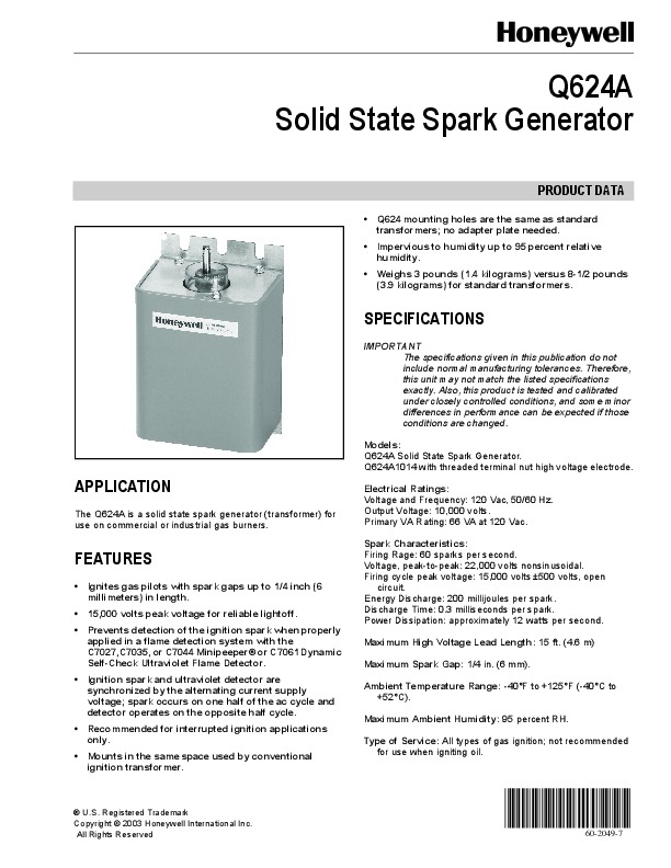
Q624A Solid State Spark Generator PRODUCT DATA · Q624 mounting holes are the same as standard transformers; no adapter plate needed. · Impervious to humidity up to 95 percent relative humidity. · Weighs 3 pounds (1.4 kilograms) versus 8-1/2 pounds (3.9 kilograms) for standard transformers. SPECIFICATIONS IMPORTANT The specifications given in this publication do not include normal manufacturing tolerances. Therefore, this unit may not match the listed specifications exactly. Also, this product is tested and calibrated under closely controlled conditions, and some minor differences in performance can be expected if those conditions are changed.
Power Equipment User Manual Free Download. Electric Generator for Power Manual. Free Manual Download PDF.
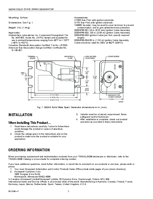
Models: Q624A Solid State Spark Generator. Q624A1014 with threaded terminal nut high voltage electrode. APPLICATION The Q624A is a solid state spark generator (transformer) for use on commercial or industrial gas burners. Electrical Ratings: Voltage and Frequency: 120 Vac, 50/60 Hz. Output Voltage: 10,000 volts. Primary VA Rating: 66 VA at 120 Vac. Spark Characteristics: Firing Rage: 60 sparks per second. Voltage, peak-to-peak: 22,000 volts nonsinusoidal. Firing cycle peak voltage: 15,000 volts ±500 volts, open circuit. Energy Discharge: 200 millijoules per spark. Discharge Time: 0.3 milliseconds per spark. Power Dissipation: approximately 12 watts per second. Maximum High Voltage Lead Length: 15 ft. (4.6 m) Maximum Spark Gap: 1/4 in. (6 mm). Ambient Temperature Range: -40°F to +125°F (-40°C to +52°C). Maximum Ambient Humidity: 95 percent RH. Type of Service: All types of gas ignition; not recommended for use when igniting oil. FEATURES · Ignites gas pilots with spark gaps up to 1/4 inch (6 millimeters) in length. · 15,000 volts peak voltage for reliable lightoff. · Prevents detection of the ignition spark when properly applied in a flame detection system with the C7027,C7035, or C7044 Minipeeper® or C7061 Dynamic Self-Check Ultraviolet Flame Detector. · Ignition spark and ultraviolet detector are synchronized by the alternating current supply voltage; spark occurs on one half of the ac cycle and detector operates on the opposite half cycle. · Recommended for interrupted ignition applications only. · Mounts in the same space used by conventional ignition transformer. ® U.S. Registered Trademark 2003 Honeywell International Inc. 60-2049-7 Q624A SOLID STATE SPARK GENERATOR Mounting: Surface. Dimensions: See Fig. 1. Weight: 3 lb. (1.4 kg). Approvals: Underwriters Laboratories Inc. Component Recognized: File No. MH7453, Guide No. JHYR2; tested and accepted for use in ambient temperatures ranging from -40°F to + 125°F (-40°C to +52°C). Canadian Standards Association Certified: File No. LR1620. American Gas Association Design Certified: Certificate No. G-140.401. TERMINAL BOARD MOUNTING PLATE Accessories: C7005 Gas Pilot, with ignition electrode. Q179 Gas Pilot, with ignition electrode. 134666 Insulator; may be used to cover terminal, to prevent contamination, and to give added terminal protection. 32004766-001 24 in. (610 mm) Ignition Cable Assembly. 32004766-002 120 in. (3.05 m) Ignition Cable Assembly. 32004766-003 Ignition Cable (per foot, specify required length). 32004766-004 60 in. (1.52 m) Ignition Cable Assembly. Cable should be rated for 25kV at 482°F (250°C). HIGH VOLTAGE ELECTRODE COVER SCREW 19/64 (7) 1-1/4 (32) 4-1/4 (108) 1-1/4 (32) 13/16 (20.5) 5-1/4 (133.5) 5-15/16 (151) 6-3/4 (171.5) KNOCKOUT FOR 1/2 INCH CONDUIT 3 (76) M20858 Fig. 1. Q624A Solid State Spark Generator dimensions in in. (mm). INSTALLATION When Installing This Product. 1. 2. Read these instructions carefully. Failure to follow them could damage the product or cause a hazardous condition. Check the ratings given in the instructions and on the product to make sure the product is suitable for your application. 3. 4. Installer must be a trained, experienced, flame safeguard control technician. After installation is complete, check out product operation as provided in these instructions. ORDERING INFORMATION When purchasing replacement and modernization products from your TRADELINE® wholesaler or distributor, refer to the TRADELINE® Catalog or price sheets for complete ordering number. If you have additional questions, need further information, or would like to comment on our products or services, please write or phone: 1. Your local Honeywell Automation and Control Products Sales Office (check white pages of your phone directory).
Wikipedia’s page for Honeywell
Publisher: www.honeywell.com