
| Categories | Electric Generator Manuals, Generac Generator Manuals |
|---|---|
| Tags | Generac 7500EXL |
| Download File |
|
| Document File Type | |
| Copyright | Attribution Non-commercial |
Owner’s Manual Parts Included* Table of Contents · Generator · Wheel kit · Storage Cover · Battery · Battery Float Charger · Battery Charge Cables · Spare Spark Plug, Air Filter, and Oil Filter · Spark Plug Wrench · (2) Locking 30 Amp Plugs · Engine Oil · Owner’s Manual · Engine Manual *If any parts are missing or damaged, call 1-800-270-1408. Safety Rules 2-3 Assembly 4-5 Know Your Generator . 6 Operation 7-12 Product Specifications . 13 Maintenance 13 Storage 14 Troubleshooting . 15 Schematic 16 Wiring Diagram .
Power Equipment User Manual Free Download. Electric Generator for Power Manual. Free Manual Download PDF.
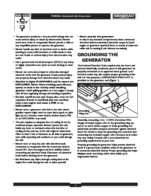
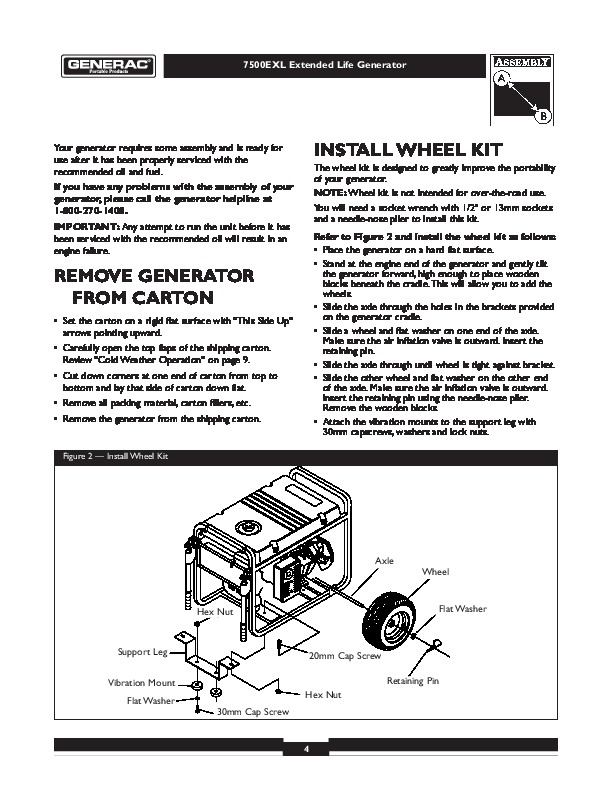
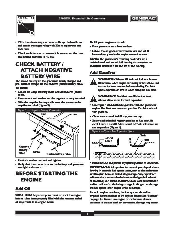
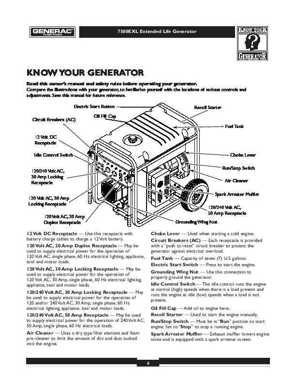
17 Replacement Parts . 18-22 Notes . 23 Warranty . Last Page Questions? Help is just a moment away! Call: Generac Generator Helpline – 1-800-270-1408 M-F 8-5 CT Web: www.generac-portables.com This is the safety alert symbol. It is used to alert you to potential personal injury hazards. Obey all safety messages that follow this symbol to avoid possible injury or death. Model No. 1019-3 (7,500 Watt AC Generator) Manual No. 189713GS Revision 0 (09/05/2001) 7500EXL Extended Life Generator EQUIPMENT DESCRIPTION This generator is an enginedriven, revolving field, alternating current (AC) generator. It was designed to supply electrical power for operating compatible electrical lighting, appliance, tools and motor loads.This manual contains information for a generator that operates 120 and/or 240 Volt, single phase, 60 Hz devices that require up to 7,500 watts (7.5 kW) of power that pull up to 62.5 Amps at 120 Volts or 31.2 Amps at 240 Volts. SAFETY RULES This generator set was designed and manufactured for specific applications. Do Not attempt to modify the unit or use it for any application it was not designed for. If you have any questions about your generator’s application, ask your dealer or consult the factory. The manufacturer could not possibly anticipate every circumstance that might involve a hazard. For that reason warnings in the manual and warnings on tags or decals affixed to the unit are not allinclusive. If you intend to handle, operate or service the unit by a procedure or method not specifically recommended by the manufacturer, first make sure that such a procedure or method will not render this equipment unsafe or pose a threat to you and others. Read this manual carefully and become familiar with your generator set. Know its applications, its limitations and any hazards involved. CAUTION! Do Not exceed the generator’s wattage/amperage capacity.The total load should not be greater than 7,500 watts. See “Don’t Overload the Generator ” on page 12. The generator’s revolving field is driven at about 3,600 rpm by a single-cylinder engine. Every effort has been made to ensure that information in this manual is accurate and current. However, Generac reserves the right to change, alter or otherwise improve the product and this document at any time without prior notice. WARNING: The engine exhaust from this product contains chemicals known to the State of California to cause cancer, birth defects, or other reproductive harm. CAUTION! Do Not tamper with engine governed speed. High operating speeds are dangerous and increase risk of personal injury or damage to equipment.The generator supplies correct rated frequency and voltage only when running at proper governed speed. Incorrect frequency and/or voltage can damage some connected electrical loads. Operating at excessively low speeds imposes a heavy load.When adequate engine power is not available engine life may be shortened. The Emission Control System for this generator is warranted for standards set by the Environmental Protection Agency. For warranty information refer to the engine owner’s manual. WARNING! You must isolate the generator from the electric utility using approved transfer equipment if this unit is used for backup power. Failure to isolate the generator from the power utility may result in injury or death to electric utility workers and damage to the generator due to a backfeed of electrical energy. Whenever unit is providing backup power, the electric utility must be notified. DANGER! Generator exhaust gases contain DEADLY carbon monoxide gas. If breathed in sufficient concentrations, carbon monoxide can cause unconsciousness or death. Operate this equipment outdoors where adequate ventilation is available. 2 7500EXL Extended Life Generator · The generator produces a very powerful voltage that can cause serious injury or death by electrocution. Never touch bare wires or receptacles. Never permit a child or any unqualified person to operate the generator. · Never handle any kind of electrical cord or device while standing in water, while barefoot or while hands or feet are wet. Death or serious injury from electrocution may result. · Use a ground fault circuit interrupter (GFCI) in any damp or highly conductive area (such as metal decking or steel work). · Never use worn, bare, frayed or otherwise damaged electrical cords with the generator. Death, serious injury and property damage from electrical shock may result. · Gasoline is highly FLAMMABLE and its vapors are EXPLOSIVE. Never allow smoking, open flames, sparks or heat in the vicinity while handling gasoline. Avoid spilling gasoline on a hot engine. Comply with all laws regulating storage and handling of gasoline. · Do Not overfill the fuel tank. Always allow room for fuel expansion. If tank is overfilled, fuel can overflow onto a hot engine and cause a FIRE or an EXPLOSION. · Never store a generator with fuel in the tank where gasoline vapors might reach an open flame, spark or pilot light (as on a furnace, water heater, clothes dryer). FIRE or an EXPLOSION may result. · The unit requires an adequate flow of cooling air for its continued proper operation. Never operate the unit inside any room or enclosure where the free flow of cooling air into and out of the unit might be obstructed. Allow at least 2 feet of clearance on all sides of generator, even while operating unit outdoors, or you could damage the unit. · Never start or stop the unit with electrical loads connected to receptacles with the connected devices turned ON. Start the engine and let it stabilize before connecting any electrical loads. Disconnect all electrical loads before shutting down the generator. · Do Not insert any object through cooling slots of the engine.You could damage the unit or injure yourself. · Never operate the generator: in rain; in any enclosed compartment; when connected electrical devices overheat; if electrical output is lost; if engine or generator sparks; if flame or smoke is observed while unit is running; if unit vibrates excessively. GROUNDING THE GENERATOR The National Electrical Code requires that the frame and external electrically conductive parts of this generator be properly connected to an approved earth ground. Local electrical codes may also require proper grounding of the unit. For that purpose, a GROUNDING WING NUT is provided on the generator end (Figure 1). Figure 1 — Grounding Wing Nut Grounding Wing Nut Generally, connecting a No. 12 AWG (American Wire Gauge) stranded copper wire to the grounding wing nut and to an earthdriven copper or brass grounding rod (electrode) provides adequate protection against electrical shock. Be careful to keep the grounding wire attached after connecting the stranded copper wire. However, local codes may vary widely. Consult with a local electrician for grounding requirements in your area. Properly grounding the generator helps prevent electrical shock if a ground fault condition exists in the generator or in connected electrical devices. Proper grounding also helps dissipate static electricity, which often builds up in ungrounded devices. 3 7500EXL Extended Life Generator Your generator requires some assembly and is ready for use after it has been properly serviced with the recommended oil and fuel. If you have any problems with the assembly of your generator, please call the generator helpline at 1-800-270-1408. IMPORTANT: Any attempt to run the unit before it has been serviced with the recommended oil will result in an engine failure. INSTALL WHEEL KIT The wheel kit is designed to greatly improve the portability of your generator. NOTE: Wheel kit is not intended for over-the-road use. You will need a socket wrench with 1/2 ” or 13mm sockets and a needle-nose plier to install this kit. Refer to Figure 2 and install the wheel kit as follows: · Place the generator on a hard flat surface. · Stand at the engine end of the generator and gently tilt the generator forward, high enough to place wooden blocks beneath the cradle.This will allow you to add the wheels. · Slide the axle through the holes in the brackets provided on the generator cradle. · Slide a wheel and flat washer on one end of the axle. Make sure the air inflation valve is outward. Insert the retaining pin. · Slide the axle through until wheel is tight against bracket. · Slide the other wheel and flat washer on the other end of the axle. Make sure the air inflation valve is outward. Insert the retaining pin using the needle-nose plier. Remove the wooden blocks. · Attach the vibration mounts to the support leg with 30mm capscrews, washers and lock nuts. REMOVE GENERATOR FROM CARTON · Set the carton on a rigid flat surface with “This Side Up ” arrows pointing upward. · Carefully open the top flaps of the shipping carton. Review “Cold Weather Operation ” on page 9. · Cut down corners at one end of carton from top to bottom and lay that side of carton down flat. · Remove all packing material, carton fillers, etc. · Remove the generator from the shipping carton. Figure 2 — Install Wheel Kit Axle Wheel Hex Nut Flat Washer Support Leg Vibration Mount Flat Washer 30mm Cap Screw 20mm Cap Screw Retaining Pin Hex Nut 4 7500EXL Extended Life Generator · With the wheels on, you can now lift up the handle end and attach the support leg with 20mm cap screws and lock nuts. · Check each fastener to ensure it is secure and the tires are inflated between 15-40 PSI. To fill your engine with oil: · Place generator on a level surface. · Follow the oil grade recommendations and oil fill instructions given in the engine owner’s manual. NOTE: The generator’s revolving field rides on a prelubricated and sealed ball bearing that requires no additional lubrication for the life of the bearing. CHECK BATTERY / ATTACH NEGATIVE BATTERY WIRE The sealed battery on the generator is fully charged and preinstalled except for the negative (black) battery cable. To install: · Cut off tie wrap securing loose end of negative (black) cable. · Remove nut and washer on the negative battery terminal. · Slide the negative battery cable over the screw on the negative terminal (Figure 3). Figure 3 — Negative Battery Connection Add Gasoline WARNING! Never fill fuel tank indoors. Never fill fuel tank when engine is running or hot.Allow unit to cool for two minutes before refueling. Do Not light a cigarette or smoke when filling the fuel tank. WARNING! Do Not overfill the fuel tank. Always allow room for fuel expansion. · Use regular UNLEADED gasoline with the generator engine. Do Not use premium gasoline. Do Not mix oil with gasoline. · Clean area around fuel fill cap, remove cap. · Slowly add unleaded regular gasoline to fuel tank. Be careful not to overfill. Allow about 1/2 ” of tank space for fuel expansion (Figure 4). Figure 4 — Typical Fuel Expansion Space Nut Washer 1/2 ” Air Space Negative battery cable Tank Fuel Screw Positive battery cable · Install fuel cap and permit any spilled gasoline to evaporate. IMPORTANT: It is important to prevent gum deposits from forming in essential fuel system parts, such as the carburetor, fuel filter, fuel hose or tank during storage.Also, experience indicates that alcoholblended fuels …..
too high. Dirty air filter. Choke is opened too soon. Carburetor is running too rich or too lean. Engine shuts down during operation. Engine lacks power. Replace spark plug. Drain gas tank; fill with fresh fuel. Open choke fully and crank engine. Contact Generac Power Systems service facility. 10. Contact Generac Power Systems service facility. 11. Contact Generac Power Systems service facility. 12. Replace battery. 1. Fill fuel tank. 2. Fill crankcase to proper level. 1. See “Don’t Overload the Generator ” on page 12. 2. Replace air filter. 1. Move choke to halfway position until engine runs smoothly. 2. Contact Generac Power Systems service facility. 15 7500EXL Extended Life Generator SCHEMATIC 16 7500EXL Extended Life Generator WIRING DIAGRAM 17 7500EXL Extended Life Generator EXPLODED VIEW ALTERNATOR 18 7500EXL Extended Life Generator EXPLODED VIEW FRAME 19 7500EXL Extended Life Generator PARTS LIST ALTERNATOR & FRAME Item 11 12 13 14 15 16 17 18 19 20 21 22 23 24 25 26 27 28 29 30 31 32 33 34 35 36 37 38 39 40 41 42 43 44 45 46 47 48 49 50 51 52 Part # Qty Description A187024GS 1 CRADLE J189176GS 1 SHIELD, Heat 92982GS 1 DECAL, Danger 92665GS 1 INSULATION, #2-1/4 ” Thick B1998GS 1 TANK, Fuel (Includes Items 12&13) B4363GS 1 CAP, with Gauge, Fuel 85000GS 1 CLIP, Insulation 93826GS 1 DECAL, Start Instructions 78831BGS 4 HHMS, M6-1.0 x 60, SEMS 83465GS 4 GROMMET,Tank 77395GS 8 NUT, Flange Lock – M6 80270GS 1 VALVE,Tank 78299GS 1 BUSHING,Tank B2153GS 9 SCREW, 12-14 x 7/8, Self Driller 43116GS 4 HHCS, M6 – 1.0 x 12 189711GS 1 DECAL, Recoil 73054GS 1 DECAL, Fuel Shut-Off 22127GS 5 NUT, 1/4 – 20 77816GS 2 DECAL, Hot Muffler 83083GS 1 SCREEN, Spark Arrester 86307GS 4 HHMS, 5/16-24 x 3/4 ” SEMS 92247GS 1 HOUSING, Engine Adapter A92531GS 1 SUPPORT, Engine 189160GS 12 NUT, 5/16-18 Flange Serrated 22129GS 2 WASHER, Lock – M8 82857GS 4 MOUNT,Vibration 22531GS 2 HHCS, 5/16-18 x 1-3/4 ” 92609GS 2 MOUNT,Vibration 22142GS 2 SCREW, 5/16 – 18 x 3/4 ” A7433GS 1 MUFFLER A92731GS 1 SUPPORT, Engine & Muffler 90239GS 1 GASKET, Muffler B1342GGS 1 ASSEMBLY, Rotor (Inclds Item 33) 65791GS 1 BEARING 96796GS 1 WASHER, Special Flat – M8 47481GS 1 HHCS, 5/16-24 x 10-5/8 B1897AGS 1 ASSEMBLY, Stator 20566GS 1 DECAL, 1-800 40976GS 2 SCREW, M8 – 1.25 x 20 92532GS 1 BRACKET, Muffler 66476GS 2 CAPSCREW, M6 – 1.0 x 12mm 189691GS 1 DECAL, Control Panel B4366GS 1 ASSEMBLY, Control Box J96068GS 1 SHIELD, Heat 14353621GS 1 WIRE, Ground 26850GS 2 WASHER, Shakeproof Ext. M6 BB3061GS 2 BOTTLE, Oil 81917GS 1 PIN, Roll 4mm x 10 B4986GS 1 DECAL, Ground 189691GS 2 DECAL, Heat Shield 56893GS 5 CRIMPTITE, 10-24 x 1/2 ” 84132GS 1 ASSEMBLY, Power Regulator Item 53 54 55 56 56 57 58 59 60 61 62 63 64 65 66 67 68 69 70 71 72 73 74 75 76 77 78 79 80 81 82 83 84 85 86 87 88 89 90 92 93 94 95 96 97 98 99 900 Part # Qty Description 67022GS 1 GROMMET, Rubber SRV66825DGS 1 CARRIER, Rear Bearing 86494GS 1 SCREW, M6-1.0 x 16 Wing 23762GS 1 WASHER, Shakeproof Ext. #10 23762GS 2 WASHER, Ext. #10 Shakeproof 66386GS 1 ASSEMBLY, Brush Holder 66849GS 2 TAPTITE, M5-0.8 x 16 B4871GS 1 COVER, Bearing Carrier 74908GS 4 TAPTITE, M5-0.8 x 10 B4767GS 1 COVER, Unit 66849CGS 1 TAPTITE, M5-0.8 x 30 65795GS 2 RECTIFIER, Battery Charge 66449LGS 4 BOLT, Stator M6-1 x 190mm 72347GS 1 SPARKPLUG 22097GS 5 LOCKWASHER, 1/4 ” – M6 189713GS 1 MANUAL, Owners 73111GS 1 FILTER, Air 84882GS 1 WRENCH, Spark Plug 43438GS 1 PLUG, 120/240V, 30A, 4p 70185GS 1 OIL FILTER A8927GS 1 MANUAL, Engine B4177GS 1 CHARGER, Battery Float 39287GS 2 HHCS, M8 – 1.25 x 45 65787GS 1 CABLE, Battery Charge 37806GS 1 PLUG, 120V/30A 189302BGS 1 WIRE ASM, #16 77282GS 1 SWITCH, Starter 188987GS 1 BRACKET, Switch 188989GS 1 ASM, Jack, DC 22287GS 2 HHCS, 1/4 – 20 x 3/4 ” 22097GS 4 LOCKWASHER, 1/4 – M6 96113GS 1 WIRE ASM, #13 J186704GS 1 TRAY, Battery B4489GS 1 BATTERY, 12V 18 AH 189302CGS 1 WIRE ASM, #13 185939HGS 1 WIRE ASM, #55 52856GS 2 NUT, M5 Flange Hex 189198GS 1 DECAL, Instruction, ES 58359GS 1 LUG, 5/16 #22/18 I-S 52618GS 2 HHCS, M5 – 0.8 x 12 23897GS 2 WASHER, M5 Flat 187104GS 4 WASHER, Nylon 22145GS 4 WASHER, Flat, 5/16 – M8 49820GS 2 NUT, M8 Nylok BB5586GS 2 HANDLE B4605GS 2 GRIP B4135GS 2 PIN, with Lanyard NSP 1 ENGINE Optional Accessories Not Included: 84883GS Cord Wrap 20 7500EXL Extended Life Generator EXPLODED VIEW AND PARTS LIST CONTROL PANEL Item 11 12 13 14 Part # BB4461GS 23897GS 49226GS 91526GS 82538GS 82881GS B4262GS 90418GS 75207NGS 75207AGS 75207GS 23365GS 68868GS 43437GS Qty Description 1 PANEL, Control 4 WASHER, #10 M5 Flat 4 WASHER, M5 Lock 4 SCREW, M5-0.8 x 12 mm 1 SWITCH, Idle Control 6 WASHER, 7/16 ” Int. Lock 1 OUTLET, 50A, 240V 1 OUTLET, 10A, 12VDC 2 CIRCUIT BREAKER, 35 AMP 2 CIRCUIT BREAKER, 30 AMP 2 CIRCUIT BREAKER, 20 AMP 10 WASHER, #8 Shakeproof 1 OUTLET, 30A, 120V Locking 1 OUTLET, 30A, 120V/240V Locking Item 15 16 17 18 19 20 21 22 23 24 25 26 27 28 Part # 68759GS 43180GS 22264GS 51715GS 64526GS 83970GS 64525GS 87962GS 84335GS 84134GS B92069GS 84028GS 43181GS 43182GS Qty Description 1 OUTLET, 20A, 120V 10 WASHER, M4 Flat 10 WASHER, #8 M4 Lock 10 NUT, M4 – 0.7 Hex 8 SCREW, #6-32 x 3/8 ” 1 BOARD, System Control 4 3/4 ” Hex Standoff 1 CIRCUIT BREAKER, 10A (automatic), 12V 1 ASSEMBLY,Wire Harness 1 GROMMET, Rubber Connector 1 BOX, Control Panel 1 TRANSFORMER, Idle Control 4 SCREW, M3 – 0.5 x 10 mm 4 WASHER, M3 Lock 21 7500EXL Extended Life Generator EXPLODED VIEW AND PARTS LIST WHEEL KIT Item 11 12 13 14 15 16 Part # B187113GS B4966GS 93693GGS 87005AGS 39287GS B186927GS 27007GS 42909GS 52858GS 22247GS 39253GS 22145GS 49820GS 187104GS B4605GS B4135GS Qty Description 2 HANDLE (Includes Item 15) 2 WHEEL 1 AXLE 2 PIN, Retaining 2 HHCS, M8 – 1.25 x 45 1 LEG, Support 2 MOUNT,Vibration 2 CAPSCREW, Hex Hd. M8 – 1.25 x 30 4 NUT, Lock M8 2 WASHER,Wheel 2 CAPSCREW, Hex Hd. – M8 – 1.25 x 20 6 WASHER, Flat, 5/16-M8 2 NUT, M8 Nylok 4 WASHER, Nylon 2 GRIP 2 PIN, with Lanyard 22 7500EXL Extended Life Generator NOTES 23 LIMITED WARRANTY FOR PORTABLE GENERATORS GENERAC PORTABLE PRODUCTS, LLC (hereafter referred to as the COMPANY) warrants to the original purchaser that the components in its portable generator will be free from defects in materials or workmanship for the items and period set forth below from the date of original purchase.This warranty does not include the gasoline engine when furnished or attached because such engine is covered solely by the engine manufacturer’s warranty. Starting batteries are not warranted by the COMPANY.The term “original purchaser ” means the person for whom the generator is originally purchased.This warranty is not transferable and applies only to portable generators driven by an overhead valve engine. Warranty Schedule: Engine All other parts Consumer* Warranted solely by the engine manufacturer 2 years (2nd year parts only) Commercial* 1 Year With the exception of European Community Countries, all units bound for export shall be warranted for One (1) Year in Consumer applications, and 90 days in Commercial applications as defined below. *NOTE: For the purpose of this warranty “consumer use ” means personal residential household use by original purchaser.This warranty does not apply to units used for prime power in place of utility. “Commercial Use ” means all other uses, including rental, construction, commercial and income producing purposes. Once a generator has experienced commercial use, it shall thereafter be considered a commercial use generator for the purposes of this warranty. During the warranty period, the COMPANY will, at is option, repair or replace any part which, upon examination by the COMPANY, is found to be defective under normal use and service**. All transportation costs under warranty, including return to the factory if necessary, are to be borne by the purchaser and prepaid by the purchaser.This warranty does not cover normal maintenance and service and does not apply to a generator set, alternator, or parts which have been subjected to improper or unauthorized installation or alteration, misuse, negligence, accident, overloading, overspeeding, improper maintenance, repair or storage so as, in the COMPANY’s judgement, to adversely affect its performance and reliability. **NORMAL WEAR: As with all mechanical devices, the generator needs periodic parts service and replacement to perform well.This warranty will not cover repair when normal wear has exhausted the life of a part or generator. THERE IS NO OTHER EXPRESS WARRANTY.THE COMPANY HEREBY DISCLAIMS ANY AND ALL IMPLIED WARRANTIES, INCLUDING BUT NOT LIMITED TO THOSE OF MERCHANTABILITY AND FITNESS FOR A PARTICULAR PURPOSE TO THE EXTENT PERMITTED BY LAW.THE DURATION OF ANY IMPLIED WARRANTIES WHICH CANNOT BE DISCLAIMED IS LIMITED TO THE TIME PERIOD AS SPECIFIED IN THE EXPRESS WARRANTY. LIABILITY FOR CONSEQUENTIAL, INCIDENTAL OR SPECIAL DAMAGES UNDER ANY AND ALL WARRANTIES IS EXCLUDED. THE COMPANY ALSO DISCLAIMS ANY RESPONSIBILITY FOR INCIDENTAL OR CONSEQUENTIAL DAMAGES, SUCH AS THE LOSS OF TIME OR THE USE OF THE POWER EQUIPMENT, OR ANY COMMERCIAL LOSS DUE TO THE FAILURE OF THE EQUIPMENT:AND ANY IMPLIED WARRANTIES ARE LIMITED TO THE DURATION OF THIS WRITTEN WARRANTY. Some states do not allow limitations on how long an implied warranty lasts, or the exclusion or limitation of incidental or consequential damages, so the above limitations or exclusions may not apply to you.This warranty gives you specific legal rights and you may also have other rights, which vary from state to state. For service, see your nearest COMPANY authorized warranty service facility or call 1-877-544-0982. Or look on the internet at www.generac-portables.com.Warranty service can be performed only by a COMPANY authorized service facility.This warranty will not apply to service at any other facility. At the time of requesting warranty service, evidence of original purchase date must be presented. GENERAC PORTABLE PRODUCTS, L.L.C. Jefferson,Wisconsin U.S.A. …
Wikipedia’s page for Generac Power Systems
Publisher: www.generac.com